Sunday, May 26th 2019


Viscosity and hydro-aero dynamics chapters were upgraded and re-written on March 23rd 2020.
| R&D Jets | Jets Plane Lift Propels Hydro | Cars Misc Fast Fees Futu ATS | Jack Answers |
| |
Hydrodynamics + tubes Sunday, May 26th 2019 |
|
| Tights |
Tube is kind of an upgrade to water turbine for boat and other vessels.
Viscosity and hydro-aero dynamics chapters were upgraded and re-written on March 23rd 2020. |
| DWT - Dead Weight Ton Dead Weight is the maximum payload of ship. It consists from the weights of fully filled fuel and water tanks, food and maximum cargo. - 1 DWT = 1016 kg ( = UK ton ). |
| Register Ton Register ton is volume. One register ton is 100 cubic feet or 2.834 m3. Ocean Ton |
| GWT - Gross Weight Ton Gross weight ton total volume of the ship. - unit is register ton. - 1 GWT = 2.834m3 or 100 ft3. NWT - Net Weight Ton |
In the picture above, there is boat with tubes for taking water to propels.When ship moves, it has to push water away. The amount of water is equal to underwater side projection of ship. The actual volume comes from the speed of ship.
General rules for aerodynamics are in force also in water, sharp and long front is the best. The water, which goes under hull raises ship. And so on.
- Water which goes under hull is wanted thing only in fast boats, whose front raises up with the speed.The push of water raises the waves around the front. In ship the length is insignificant. After front has made the front wave and hole into water, the water starts to fall back. After water has fallen to normal sea level, the length becomes insignificant. Water pushes the sides with steady water pressure.
The fall back takes place soon after ship has reached the full width. In theory : After that the water pressure falls a little all the time, it doesn't have any meaning in practice.
Hydrodynamics in the back are simple. If you narrow the boat too quickly, the rear starts to drag ship backwards. There is a hole in the water, because water does not have enough time to fill ship's hole. When going forwards there are two things in the back. When the outlet leaves the water to the back of the ship, it creates turbulences and overpressure. When you use long outlets, which comes out from the hull, there aren't turbulences, neither is there overpressure system, which pushes ship forwards.
- Turbulences disturb hull's hydrodynamics, the smoothness with what ship leaves it's hole.The tubes in the picture takes part from the water, ship has to push, into propels. In principle the speed of water at the front is 0 m/s. The tubes move the speed from propels to front.
Tube moves the propel speed into front. To a place, where ship makes the hole to itself. The speed of water at small propel must always be bigger than the speed of big vessel.
If propel speed-area-pressure system is not as big or bigger than vessel's speed-area-pressure system, vessel doesn't move.The force, propel has to beat comes from the force, with what water resists ships hole making. It depends on waters resistance / viscosity, speed and front's hydrodynamics.
- The long and sharp front reduces the amount of water, location X in the hull has to push in one second. It is the same in aerodynamics and with gases.Hulls have water resistance factors, they are equal to cars and planes air-resistance factors.
Ship's over water body needs aerodynamics after speed exceeds 20 knots / 40 km/h. Need grows with top/cruising speed.
Good traditional hull creates only front waves. Ideal hull with tubes doesn't create waves, only small turbulences in the back.You can build a rudder / helm in front of the tube. With front rudder, you can steer the ship also with inlet water. You must always place the turn mechanism to the front of the rudder. Even then, when you move the front of the rudder. You can do that with ring system.
In principle, you should be capable of creating a tube hull, which doesn't raise waves. At least during heavy accelerations.
Major front wave is born, when speed is too big. Water doesn't have enough time to escape the ship. When so, wave is born after hydro dynamics cease to work properly.
It means, that you should be capable of sucking the whole front wave into tubes, without increasing the speed.The more you get away from front wave, the more power you use to speed creation.
Water lasts easily around 200 bar pressures. When fast, powerful boat accelerates, the pressures in the tubes can raise a lot.
If you take more water from the front, than it is needed for displacement, the additional inlet water accelerates boat.
Additional water creates a hole and under pressure system in front of the boat.
What was objects kinetic energy ?
It is an energy charge object has when in moves. You charge it with acceleration and maintain it with steady speed and direction. When make curve, you change direction your kinetic energy charge. Change of direction needs energy, just like hike in amount of kinetic energy charge. When you release gear and let the car roll, it rolls with it's kinetic energy charge. It uses the stored kinetic energy for beating driving resistances.Idea of varying acceleration energy, you need for charging the car and it's passengers, comes from curves. Energy you need for curve grows with turning angle. Acceleration unit is meters per second in power of two. Centrifugal force is mass x speed in power of 2 per turning radius.
Acceleration-deceleration misses defined force. Acceleration is 2 x length / time in power of 2... speed in power of 2 / 2 x length ... speed / time.
With letters centrifugal force is Fct = m * v2 / r
- acceleration is a = 2s / t2 = v2 / 2s = v/t, where v is change in speed
- acceleration work is m * a * s ... m * v2 / 2, and acceleration power-force is m * a * v.Fct = kg + m2/s2 + 1/m = kg + m/s2
Wa = kg + m/s2 + m = kg + m/s2 + m = Nm
Pa = kg + m/s2 + m/s= kg m2/s3Newton meter is Newton per meter, not Newton per second like usual.
In order to convert this Nm into N, you need average speed from accelerationFa = m * a / va
Air space
When hollow thing is in water, it's capability to carry load is dependent on under water air space.
When 20 m3 water weighs 20 000 kg, 20 m3 air weighs only 2.6 kg.
When so, the hollow space can carry 20 000 kg - 2.6 kg = 19 997 kg load.From this 19 997 kg you must reduce the weight of the hull ( hollow object ).
When you put more than 20 000 kg weight into hull, it sinks until the air space is big enough for carrying the load.
When you put thing into under water air space, the thing reduces the air space with it's volume.
When you put things, which are lighter than water, into underwater hull, you get a density bonus from these things.
Oil's density is around 0.835 kg / liter, when so you get 1 kg - 0.835 kg = 0.165 kg bonus from the underwater oil. System goes also to fuel tanks.Easiest way to do air space calculations, is to fill under water hull with some known thing, like steel.
After you get payload for one thing, it works with all. The density system balances the underwater air space system.- Principle is the same with water and gases. Air ships and space lifts are calculated with the same system. Only the carrier is different.
- Air space calculations are applications from Archimedes discoveries.
- Air space gets help to the lift from the later water's internal pressure system.- - - -
Inflatable swimming aids use airspace for keeping you on surface.
When you mount swimming aid to your or your kid's body, the aid becomes part of body and it's air space.
When you float on your back in water, your face, mouth and nose are the topmost parts in your body.As we all know, human body doesn't sink into water without weighs in your legs.
Human body's average density is almost exact match to water.
Drowning is always result from panic / lack of experience from the water.
Pressure system
It is also possible to calculate displacement with bottom pressure / lift.
With big displacement depth, water's internal pressure must be taken to notice.With bottom pressure you get the bottom force, which pushes ship upwards.
Freely floating ship sinks, until the bottom force is big enough for carrying ship's weight.
Bottom force is pressure x area.From the speed swimmer and ship gets additional lift. Lift comes from water's viscosity.
Viscosity and slowness in hole making increases the bottom pressure.
Weight system of the tube
The weight of water in the tube belongs to payload.
If you build the tube into air space, it will crack, if it cannot carry the weight of water in the tube.When so, you must always minimize the tube sizes and maximize the speed-pressure system.
You always drag the tubes to via bottom plate. Like in this picture.You can lighten the load with picture like partial tube. You must continue the tube under hull, to the end of the ship.
Otherwise you create forces which resists the movement. The water you push under hull raises ship. Steering is difficult.
Another way to cut the tube is tilted hole, which ends soon after outlet pipe. it has better steering, but poorer power.You can build tubes to the both sides of the ship. These tubes on the sides can be used for steering. And-or moving.
Good system for small / short boats, where the underlying tube-system is short, and ship can be steered from the back.
The pressure and push vanishes rather quickly from the underlying tube : steering in the back loses lots of power.
Tube sheets - 26th March 2020
Lotus - 123 .. Excel - XLS yve_tubes_ship1.WK4 yve_tubes_ship1.XLS - calculates tubes and resistances for water and air. Suits to boats, cars and planes
Sample for tube and water resistance calculations - 26th March 2020
In the sample ship :
- The length of ship is 20 m.
- The under water hull area is 5 * 1.5 m = 7.5 m2.
- The hull area from tube-to-tube is 3 * 1.5 m = 4.5 m2.
- Area for tubes is 2 x 0.5m x 0.5m = 0.5 m2.When ship moves 10 m/s, the volume-to-push for 1 second is 75 m3.
With 50% removal ratio, size of volume-to-push halves to 37.5 m3.- when you design tubes, you must remember, that can suck water from the bottom of the hull. When you upgrade ship with tubes, you must check with underwater hull model and basin the bottom pressures and lift.
In order to move 37.5 m3 volume with 0.5 m2 tube area, speed and length of logical volume in the tube must be 37.5 / 0.5 = 75 m/s.
Logical volume weighs 37 500 kg. If water's internal friction is 0.001, friction force is 0.001 * 37 500 kg * 9.81 m/s2 = .368 N / m. When boat is 20 m long you do this 368 work for each meter, when so the pump force is 20 m x 368 N / m = 7 360 N. This force converts into 7.4 kWs or 10 hp power demand. Not known how realistic internal friction factor is.
At the end of the hull you push the water into pit, the hull lefts behind. This calculation is for required tube power only. This tube reduces the required engine power and adds the pump power into engine power. The 50% removal of frontal water leaves another 50% to front. From this halved volume escape viscosity moves 25 %, another 25% must be removed with engine power.
Push-to-sides goes with another formula. Fr = 0.5 * q * y * A* v3.
- 0.5 = escape viscosity
- q = average density of water ( kg / m3 )
- y = vessel's water resistance co-efficient factor ( might be in range 0.01 to 0.3 )
- A = cross section of vessel's under water area ( m2 )
- v = vessel's speed ( m/s )Average density of water is calculated with underwater height. Surface density of water is 1 000 kg / m3. At one meter density grows with overlying weight, it is 2 000 kg / m3. When density-pressure system at 1.5 meters is 2 500 kg / m3, average is 3 500 / 2 = 1 750 kg / m3.
0.5 * 1 750 kg / m3 * 0.1 * 7.5 m2 * 103 m/s = 656 250 N. This converts into 656 kWs or 900 hp power at 20 knot speed.
The sample boat is 5 meter wide, fully loaded old yacht. Used by Moldavian smugglers.
Front wave is the only escape you have
Although front wave was mocked before, it is the only escape, water has. You cannot compress water like gas.
Therefore around 99% from the water, ship pushes, comes up. Into front wave and overall local hike in water levels.
System is better explained in dam and river basins operating principles.In the picture there is principle for creating a good hull for a big heavy ship. Like for example oil-train ferry.
When ship has clear, visible bottom plate, you should never widen the sides of underwater body.
You should keep the body straight or narrow it a little towards surface.
When you narrow body a little, the area into which the water expands is bigger.Another thing in big hull is, that you should keep the underwater height as low as possible.
Pressure in water grows very quickly. The deeper you go, more difficult it is to open the hole for ship.The bumps on the sides ... in the picture ... are in principle good places for additional air-spaces. They create "ropes", which hangs the ship on surface, outside the hull.
When ship needs additional air spaces, they should always be on the sides, front and back. The oil-train ferry sunk after trains payload rose from 72 000 tons to 122 000 tons.If you have difficulties in keeping the low height ship up, you should use old fashioned long, sharp nosed, narrow keel system.
Old fashioned long keel takes advantage from big pressure at bigger depths, then it minimizes the work you have to do for creating a hole for it and keeping the ship up.
Big balls at the lowest levels are worst imaginable things for ship's hydro dynamics.Submarines are good sample from this. Submarine always reaches it's top speed on surface. The deeper you go, the slower your submarine goes.
When you design the tubes for propels, tube should fall a little on it's through the ship. The fall raises the ship a little.
Then the deep water at the end of tube improves the push, the ship gets from propels. Improvement comes from higher pressure-resistance system.In the future cargo ships turns more into oil-train ferry like ships. Instead of containers, you haul double track railway cars.
Cars are quite a lot faster and handier than containers. Then you need air space in the underwater body, loosely packed cars are not a very big issue.
Removing front wave with tubes - 27th March 2020
With tubes you can remove liquid-gases front wave from moving vehicle.
When you load liquid-gas into tube, tube sucks the air from front. The volume of the removed liquid-gas grows linearly with speed. This removal of liquid-gas creates force system, which is powered with a pump in the tube. It can be calculated with tubes formula. You calculate volume for the sucked liquid-gas. Then you calculate average distance to move. If you have slightly overlapping area, you can ignore the overlap. Strong overlap increases the distance to move. In 3D cube distance is obviously length of side. If it is not, it is shorter than side. Usage of side length doesn't end into lack of pump power.In the back you have third force system, which must be powered with pump. The force to beat depends on side and bottom pressure at outlet. In common tube, the force system can be negative. There is vacuum, which liquid-gas from the tubes. Force system for a tube, which doesn't move the vehicle, should be small and insignificant for pump power.
Tube, which powers the vehicle got to suck additional liquid gas into tube. Power tube takes the power for move from surrounding liquid-gas. The push power or thrust comes after liquid-gas leaves the tube. The demand for additional liquid-gas comes from escape viscosity. Which is around 50% without table data and push power enhancers.
Required volume for actual power creation grows linearly. Growth of required power can make the required volume grow faster. Tube system reduces the speed related hydro and air resistance, which grows with power of 3.
In power tube you don't reduce resistance, you create power for beating the resistance. The lowered resistance is a bonus from power creation.
- - Lift and tubes - -
If you take "all the air" from the front, you must lead part from liquid-gas to the bottom. With bottom outlets, you create lift for the vehicle. If you have cargo ship or plane, you might want to boost lift force with adjustable bottom outlets in the tube system. When vehicle is fully loaded, you bargain from cruising speed and boost the lift. When vehicle returns without full load, you increase cruising speed with rear outlets. In ships you can alter weight-center height with bottom tubes. The creation of lift needs quite a lot of additional pump power. The pressure in outlet tube matches lift pressure. With design it is possible to create low pressure points into bottom.
Weight center
Weight center should be slightly below water level.
- When center is above sea level, center boosts waves and sways the ship.
- When center is at the bottom, center pushes the ship into big wave.Every time wave comes over lower hull, common ship takes water inside.
Long telescopic keel is better way to reduce swaying than low weight center.
When you end into big storm, you must give up from comfort, and let the ship sway with waves.
With telescopic keels you can adjust / optimize the swaying in storms.Not very rare that long distance ship ... ocean crosser ... ends into unexpected big storm systems.
With the fast tube ships it is possible to escape many storms.
Tube ship with gearbox can have considerably bigger top speed than cruise speed. They are much like private cars.In lengthwise, weight center should be in the middle, or after the middle. Depends on the ship / boat.
V-Bottom and water's pressure system
The magic of V-shaped bottom is the pressure, which grows with depth. The angle, with what water pushes hull, comes with 30-45 degree angle*.
V-shaped hull redirects part from the water's push into lift.You should never widen the underwater hull after front design.
Pressure grows almost linearly. One liter water weigh 1 kg, at 10 cm depth pressure is around 100 N. At this depth, square meter has 100 / 10 x 10 boxes.
At 50 cm depth the pressure is around 5 000 N. One cubic meter water weighs 1 000 kg. At 1 meter depth pressure is around 10 000 N.Pressure system makes it also important to keep underwater hull as low as possible. The deeper you go, more power you need for moving a ship with same weight.
If you want to reduce ships swaying in side and cross waves, you should use long narrow keels. Possibly telescopic keels.Pressure sets a demand to keep lower front narrow. You should never put big balls into front, at the floor level.
This pressure system shows well, when you try to dive into deeper water. After few meters water starts to resist your attempt to go deeper.
The resistance comes from this pressure system.* Have never seen any data / calculations from the angle. Possible that the actual angle is not yet checked.
Double hull / Catarman
Double hull boat's magic comes from an open air-space in between legs. The open space has gas spring, which carries part from ship's weight. The gas spring keeps the underwater hull higher and in smaller hydrostatic pressure system. The gas spring hole doesn't resist movement as much as water.
When you design double or triple hull boats, you must always cover legs throughout the ships length. Holes in the legs disables the air space. Holes in the roof / 1st deck are in than holes in legs. It is possible to build a cheap and light systems, with what you can adjust the spring effect. One way is adjustable breaker plate at the end of the hull. Flat floor plane like walls in the front and rear gives ship's open bottom a small over pressure and small over pressure area under the over water hull..
All advantages of catarman comes from this big thing ... in between the legs. The air space allows ship to be light and fast ship, with big payload and low displacement depth.
Open air space makes catarman dangerous in big storms / waves. Big wave can close and fill the air space. Air escapes water and ship sinks quickly, sinking begins from the front.
Hydrofoil ship and raised front
Ship with underwater carrier wind ( hydrofoil ), and boat which raises it's front to the air ( when speed raises enough ) reduces the front wave formation.
The underwater wing does not have to push much water. Wing works in water with the same principles than in air.
Raised front reduces the displacement depth. Raised front needs V-shaped underwater hull, then you got to place the longitudinal weight center to back.
The underwater front design must support the raise. The front must go deeper into water with distance. The raise comes from the created front wave.When speed grows, engine-propel system pushes the rear downwards. The front design allows the front wave to slip under the hull.
When front wave goes under the hull, the boat's front raises to air. The propel and front wave creates an angle.
When boat moves, the escaping front wave ( from the moment X-1 and earlier ) fills the possible hole in between the wave and propel.
Propel
In the picture you see how red water drop moves, when propel rotates.Speed depends on the rotating speed of the propel.
When drop comes to wing, the speed is zero ( or the speed which comes some other source )
At the propel, drop moves as long as it is at the wing.
After wing, the following water drops push it farther from propel.In propel, which misses tube or ring, water starts to escape, right after wing starts to move it. In tube and ring water cannot escape until the tube-ring ends. The escape comes from liquid-gases escape viscosity. Escape viscosity is announced with percentages from incoming flow. Without tables escape in sideways is 50% from the axial flow. The escape comes from liquid-gases internal movements, density-pressure-speed doesn't have much meaning for the escape.
The movement of drop pushes ships and planes forwards.
The area of the wing, says how much water wing moves. Wing systems, whose areas are bigger than tube's are possible. They suck water from the front to the tube.
In tubes and rings propel wings can be mounted to ring / tube. You can make lighter wings or increase their maximum power ... pressure-speed system. With propel ring it is easier to build propels, with adjustable wing angles. Wings top mounting gives strength and stability to wing. With wing angle you adjust speed of the vessel.
Double-piston power system
Tubes allows you to use double piston system like "pistons-with-valves" as propellers.They are at least as efficient as paddle / drum propels. The push force is equal to stroke, pistons diameter and speed.
The ship's speed is equal to piston's speed. The water's escape and expansion at the end of the tube reduces the speed.
System doesn't leak powers-pressures in the tube ... to the unwanted directions.Pistons don't need switches for converting movement to rotation. You use rods for connecting cylinders.
Pistons are not as vulnerable to big objects in the tubes as common propel.Works in water and also in deep water. You need 4 tubes for smooth push.
You can use water's flow to open and close the valves.
When you move pistons towards front - against the flow - valves are open.If you have caps at the ends and you empty outlet tubes, you can build a tube network into ship. Without displacement cost.
Demand is that volume of the unused tubes remains at the same levels all the time. When you do that, the air space and max payload are unchanged.If ship has enough power and you need gears for adjusting speed, you do that with tube network.
When you reduce outlet tube's diameter, the speed of water / ship grows. Gears in ships work much like they do in cars.Next generation power plant and power transmission system for big ships.
With tubes and new power system, oil-train ferries can travel with the same speed than double-track oil-trains ... including the black smoke on the water.Double piston system can be used water as water pump ... system for pumping or creating pressures to liquids.
You should not use electric motors with double piston propel. When you brake or accelerate double piston system doesn't slip like propel.
Electric motor doesn't suspend excessive power demand like combustion engine does.
If the ship is accelerated or braked too much, electric motor either stops or blows up.
Double piston system allows to build a reversed push system into cylinders.? Double piston system has it's origin in my graduation work. It had originally an engine, which used liquids instead of crank system.
Gear box for double piston system - 24th November 2019
Gearbox can be made by adjusting stroke lengths of pistons. You build a rod system, that adjusts pistons movement during one push from engine. System can be made as step-less or stepped-geared system.
Screw propel
In tubes you can also use screws for transmitting engine powers into tube and water.
They are also very efficient, when compared to propel.Screw leaks a little, it needs rather big rotation speeds. Ship's speed comes from the wings tilt angle and diameter.
Suits well to smaller ships and boats. Screw can be mounted from both ends.With the multiple wings, you can reduce the leak. Two or three rounds should be enough.
If your race boat needs gears, you use car's gear-box like screw system. You have for example 4 screws for different speed ranges.
You can compress ... speed up ... the water with progressive screw. Use smaller outlet tube after compression.
Compressed tube has poorer reversing powers.- - - -
Tube-boat can have after markets engines and screws. In order to get these, you need standard mounting for engine, standard for connecting engine to screw. Then you need few standard tube sizes and mounting systems.
It is possible to equip outboard engine with short tube and screw. Alternative to a ring, which surrounds propel.
It is possible to build a screw, where tilt angle and speed can be adjusted. Tricky. Possible with at least screw, which has only one round.
Double propel tubes
In this picture there is tube system with two propels.When you have a tube system in ship ( aircraft or vehicle ), the speed and pressure system in the tube is stable.
It is not possible to build a jet engine like water jet. You use the first propel system for creating speed in the tube ( compressor in the jet )
Since the speed and pressure system is stable in the tube, the second propel must have the same pressure-speed system than the first propel has.System with two propels at the same axle should get additional water for the second propel. If you reduce the size of the tube after 2nd propel, system might work. We'll see.
In tube system, picture like 2nd propel, with free access to water at the back, would create forces which drags ship back wards.When you increase the speed of outgoing water, with 2nd propel, you increase the speed of ship.
Gear box for screw propel- 24th November 2019
With multiple screw elements you build a gearboxes to screw propel. You place all screw elements in to tube. Then you build by-pass channels for 2nd and latter elements. The highest or cruiser gear uses all elements. Lower gears open bypass-channels, from last to 2nd. When you open last element first, you can have fixed rotation speeds in all screw elements.
Tubes in planes
Copter car, next generation propel planes and copters uses vertical tubes for creating under pressures.
- Copter and copter car creates over pressure system under rotor and under pressure system over it.
- Single engine propel plane creates ship like hole to the front of the plane.Possible to build "hole-maker" air inlet systems also to jet planes. Difficult, but possible.
One way would be ship like tube in the body.
If you compress the air in the tube, you can move air to the back of the plane.With 1 / 10 compression plane with 10 meter wide round body needs 2 meter tube, for sucking all the air from the front.
Gas speed in the tube must always be slightly bigger than planes speed ... could use the system in slow airships ... special copters.Could use 3rd / 5th jet for powering the tube. 3rd and 5th engines are always over the body.
With tube, which takes air from the front, you take all the air from the above. From the beginning to end.
In flat floor plane, you might want to test one jet in the front, below the floor.Movie like combined air&space crafts, which flies from the ground to space, need special engine and wing systems.
Cold jet power transmission for aircrafts
In the air you must always compress the air. In the picture you see cold jet engine's principle.
Cold jet uses progressive screw for compressing the air, but it doesn't burn the compressed air with fuel.You power the screw with outer gear system. You power the gear with combustion engine or electric motor.
In gas, the type of power source doesn't matter. Gas suspends when needed.Cold jet compressor is quite a lot simpler than jet's compressor.
This compressor simply slices the air in the front and puts the slices into compressing wing system.It is up to you, where you lead the outlet tube.
Cold air jet can have screw propel like gears.
- it can have more than one screw per tube.
- it can have gears in powering system, too.With fully resolved Archimedes loop, you can easily build coned screws, which narrows towards ends.
They can be designed and manufactured without troubles. You can use CAD-CAM.Cold jet suits to small planes with combustion engine and copter cars. In mass produced copter car engine is always on the roof. It makes flying easier.
Cold jet should be quite a lot better than propel.
Screw is not necessarily very good in power creation. In jet you could use the screw in compressor, but not necessarily in turbine.
Tubes in cars and ground vehicles ( fixed 24th November 2019 ).
In cars and ground vehicles power which moves comes from ground and friction. The compression and manipulation of the air results into power losses.
In ships and planes you use tubes for moving the place, from where you take the power. You use power creation for reducing forces, that resists the movement.In ships and planes you always have to take water / air for moving the vehicle from somewhere. With tubes you optimize these places.
In cars you can use tubes with cooler air and combustion collectors. With cooler you can already create a vacuum, which should have an effect to air resistance.
You suck air from the front, redirect it to sides or back. In long vehicle you need longer lengthwise outlets for redirected air. You can build shapes, where outlet at the side or rear pushes vehicle forwards. With redirected air.
In high speeds, when air resistance grows to sky-high levels, you can also use engine power for sucking the air. At some speed, sucking always becomes more efficient than wheel power.
Gearboxes
From the cars we know, that top speed of gearless is only around 40 km/h / 20 knots / 25 mph.
The rpm range limits the speeds. Gears speed range is 40-60 km/h.
No matter how powerful your engine is, the rpm limits the speeds.Water is good surface for vehicles, ground vehicle speeds should be kids play to a boat with gears.
In double piston system you can use variable stroke length as "automatic" gearbox.
It is possible to build screw propel like element based gear boxes to planes.
Dynamic Viscosity - March 26th 2020
|
Escape Viscosity - March 22nd 2020
Escape viscosity is force system for sharp 90 degrees curve. When you push straight plate in water or air, water and air moves sideways and makes space to the plate slower than you move the plate. Escape viscosity is the thing, which keeps planes in the air.
Viscosity is the force you need for liquid's or gases horizontal movement. Without table data viscosity force is 50% from the objects potential energy. This default comes liquid-gases internal 45 degree forwarding angle. In water like freely floating liquid and air like freely floating gas the internal resistance is almost non-existing.Viscosity table should present factors, with what you either correct or replace the density based system. Viscosity is needed with stiff liquids and semi-solid state materials. Lubrication oil and lubrication grease are samples, which doesn't follow floating liquids and gases density system.
Air and water have shared resistance formula
Fr = 0.5 * Da * v3 * W * H
- Fr = Resistance, 0.5 = dynamic viscosity factor, Da = density of gas-liquid, v = speed, W = width of effective area, H = height of effective area.- In the formula 0.5 should be connected to air's density. 0.5 is air's horizontal viscosity. It comes from internal around 45 degree angle. Horizontal move of the air needs around 50% from the force you need vertical lift. Force you need for vertical lift is weight * density * G. When you drive in hills, you should correct this 0.5 with hills angle.
Kinetic viscosity ... escape of the air-water ... is powered by pressure on the object. When speed grows, the raised pressure automatically increases the amount of escape ... on the sides, bottom and top. In gases the escape effects to affected pressure-volume system. In liquids pressure raises, without significant fall in volume.
Rounded corners on the sides and bottom makes the escape easier. Sharp curve creates a resisting pressure system. When flow hits the corner, it bounces against the flow. Force vector for sharp 90 degrees curve has 45 degree angle. In rounded curve the summed resisting collision force is smaller than in sharp curve.
The missing round shape at the bottom, brings the magic to flat floor planes / air crafts.
Viscosity in water
At 4C water needs 1 500 N/s force for a move to sideways. When direct movement is around 1 000 N the efficiency of the move in sideways is 0.5.
When so, from one water cubic meter 500 kg / 0.5 m3 escapes in one second.This means that, when ship moves with 1 m/s speed, tubes must remove 500 kg water / m2 from the front wave per second. 10 m/s needs 5 000 kg removal.
In power transmission this means, that tube works with 50 % efficiency. 100 kW propel power gives 50 kW move power.Oil ferry sample
Oil ferry ( 100 m x 200 m with 12 m displacement ) needs 60 000 ton tube system : full length double speed pipes.
Weight is equal to oil-train. Too much, you got to use bigger pressure-speeds and short tubes.
With 10 meter inboard tubes and four times bigger speed-pressure, tube system weighs only 750500 tons.Possible that tube system at the floor level is free of charge, the water inside the tubes doesn't increase the payload. Loose open tube doesn't charge from the water inside.
The water in tube should load ship with the additional weigh per m3.Since water doesn't compress, the pressure-speed system doesn't add water's density much.When you make the curve towards the bottom plate, the force, which pushes ship up, neutralizes in the curve, which straightens the tilt.
Properly made tube-propel system is immune to speed. In at least principle it is possible to build a ghost ship, which doesn't leave waves.
Possible to build bilge pump safety systems to the tubes.
- Tubes can remove busloads of water, which leaks from the weldings ... and also from more visible holes ... in your Caribbean cruiser.When you turn big and long ship with propels in the back, the forces at the front of the hull are enormous.
If ship is 200 meters long, the front forces are almost 200 times bigger than forces at the propel.
When steel suspends and twists under these forces, it tends to break the weldings.The big over 600 m oil ships will have power outlets for tubes with 50 - 100 meter interval.
** System misses the pressure system, which comes from depth. **
? The viscosity factor ( Pa * s ) converts directly into force for one cubic meter move with 1 m/s speed. ( one square meter moves 1 meter and forms 1 cubic meter cube ).
-- --
The measured low temp value fits to the earlier internal pressure system. However, the escape efficiency improves very quickly. At 20C viscosity factor is 1 000 N/s,
800 at 30C, 650 at 40 C.After around 24C, the escape force matches gravitational drag. It is possible for water to climb hills, hurricanes and typhoons.
It is very difficult for water to raise into air at lower temperatures. On the other hand, 24C is obviously the highest temperature water has in the nature.You should keep in mind that lake/ocean water cools very quickly after surface ... with depth.
Possible that earth's cloud system works only at warm areas near equator. Then humidity condenses to clouds in random places.
Viscosity in air
At 20C temperature air's viscosity is around 18 N /s, Air weighs 1.3 kg / m3, it makes 12.5 N. Air has also around 0.5 escape efficiency.
Air needs more power, when temperature raises. At 100C you need 21.8 N.Air escapes into all directions. Viscosity could downgrade the force / resistance with 50%.
When so, wings lift is 50 % from the displaced volume ( which created over pressure under the wing ).
In ground vehicle viscosity halves air resistance force.Air forces are only 1% from hydro forces. In good and bad.
The speed-volume system for water and air
When object moves in water or gas, the movement creates a logical volume, whose length is a match to speed.
- This logical volume is the size of hole, object must make into atom mesh during 1 second time.
- Size is this volume grows linearly with speed.This volume is logical, it is created during one second time. The hole has a surrounding logical affected volume.
When you increase speed, the one second logical volume grows in all directions. Height, width and length grows linearly with speed.
The power three in air and water resistance formula comes from this linear triple growth.The actual shape of logical volume is ball and elliptic ball. Unfortunately elliptical ball seems to have exceeded mathematicians capabilities, auch, auch, auch ... .
How to calculate volumes for elliptical balls
Volume of the ball is width * height * depth, just it is with boxed volume.
- The difference is, that you calculate two areas for the rounded shape. Ball is simple it is 3.14 * r3.
- In order to calculate volume for elliptical you need formula for calculating volume with two areas.
- When you calculate two areas for the box, both areas have one shared side.
- When you multiply areas together and divide the result with shared side, you get volume with areas.Since area's calculation system for boxes and balls are the same, this aerial volume calculation should be valid balls and ellipses.
When you play with balls, you must remove radius and pi from the result. Volume calculation has 3 parameters, but aerial multiplication has four parameters. When soV = (a * b) * (b * c) / b ==> V = a * b * c
V = (3.14 * R1 * R2) * (3.14 * R2 * R3) / (3.14 * R2)
- formula simplifies into form V = 3.14 * R1 * R2 * R3The aerial volume calculation should work as long as you have one shared side for two areas. You must always be capable of removing one known and shared side from result.
Continuing with hydro and aero dynamics. And general hole system. As you can see from picture, the end of logical volume consists from two balls. Width of horizontal ball is dependent vehicles width. Vertical ball gets base for it's size from height. In cars the top is near ball, like in the diagram.
The affected volume-pressure system is rather independent from everything else but speed of object. When ground prevents the blue arrow force creation, the force spreads to red-green-magenta arrow systems. Same happens completely blocked yellow force. The body of moving object prevents birth of yellow system. In reality yellow force spreads to all the other sub systems.- Right after vehicle has punched the hole, the affected volume starts to shrink. Shrinking takes place with the power of possibilities.
- The pressure which goes to back falls always with power of 3.
- With an exception of flying aircraft, sides, floor and bottom can have reduced escape speed.After hole creation, body carries created over pressure. Violet side forces doesn't have much effect to resistance. Green roof force increases vehicles weight. In ground vehicles and catarman ship blue force need compression work, after compression blue system lightens the vehicle. At the rear the vehicle leaves a vacuum pit behind. This pit drags vehicle backwards. In short vehicle you fill the pit with over pressure, which comes to back via sides. Long vehicle loses the over pressure before end, it fills the pit with common air. Tube vehicle fills the pit with gas-liquid it removes from the front.
When viscosity is 0.5, escape speed is 50% from volume creation speed. If car moves 20 m/s speed, the pressure escapes with 10 m/s speed. In deeper water, density-pressure system keeps the formula valid.
When you have tilted front hood or roof it slows down the hole creation. It allows the creation yellow arrow system. During raise time part from initial air escapes.
In ground vehicles you should direct as much stuff to sides as possible. Same goes to over water parts of boats and ships.
In underwater hull, you maximize the lift with flow to the bottom. If you don't need lift, you should direct water to sides.
In air crafts you typically direct as much air to the bottom as possible.When you need lift ... in water or air ... with design you can build systems, which slows down the escape.
Flat floor bi-plane has escape brakes in it's construction.
- it is possible to grab more air to long flat floor hole at the bottom.
- bi planes upper wings doesn't leak air sideways. Upper wing must be made so, that it doesn't create over pressure over the lower wing.
 Measuring air-resistance and drag forces with high precision ( Labs
at Santta Claus Field Facility )
Measuring air-resistance and drag forces with high precision ( Labs
at Santta Claus Field Facility )
You could use a special railway system for measuring ground vehicles actual air-resistance forces.
You push / drag the railway car. The coupling measures the load from car.
2 liter engine needs 25 liters air in one second at 6 000 rpm. You can drag the air from filter's inlet with pump.
Moving the vehicle is the only way to find out how air reacts to the object and it's speed.For friction system, you tow the car in air tight box. The coupling measures the forces.
Before putting ground vehicle into railway car, you measure it's own forces.
Track could be in a pit, and measured object on ground level. Railway car should cover sufficient length from the pit.High speed air-resistance and friction needs, that you have a long track without any tilts.
You can make the coupling sensor with strong spring. Spring needs a chance to calibrate it.
- Could also make tilted tracks and track with a change to chance the surface.Max speeds should be at least 320 km/h / 200 mph.
Table on the right shows measured fuel consumption for 2 liter Toyota Verso 2010. Extended the measured curve to 200 km/h. Fuel consumption grows quickly after the air resistance starts to effect.
- The intended 160 km/h or 100 mph speed limit for 4 track highways increases this cars highway consumption from 7.2 to 11 liters / 100 km.
- When you increase 2-track highway speeds from 90 / 55 to 110 / 70, you get more power for the fight against global warming.Only way to increase humidity with oil, is to burn it.
GOT IT [ 5th July 2019 ]
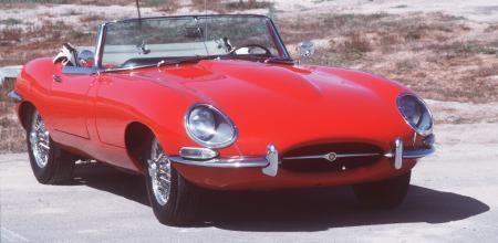
Found measured fuel consumption for 1961 Jaguar E-type. Test was made by British Autocar magazine in March 1961. Consumption is for coupe.
The mpg consumption is in UK units. UK gallon ( app 3.7 liters ) is smaller than US gallon ( app 4 liters ) . 20 uk-mpg refers to bigger consumption than 20 us-mpg.When you raise speed from 50 km/h to 180 km/h. E type only doubles the consumption. Verso doubles the consumption at 110 km/h.
E-Type has much more better aerodynamics than Verso. The aerodynamics effects to the relative increase in fuel consumption ( with increased speed ).
At highway speeds most from the increase comes from air resistance.
mph mpg-uk km/h l/100km 30 32,00 48 8,92 40 32,50 64 8,68 50 30,50 80 9,29 60 28,20 96 10,01 70 26,50 112 10,73 80 24,50 128 11,58 90 22,50 144 12,66 100 19,00 160 14,95 110 16,50 176 17,25 1961 E-Type has only 4 gears, engine goes into efficient rpm range at 40 mph / 65 km/h. Car consumes a lot in city traffic and city speeds.
Imperials
From the below you find some commonly used imperial units. Ounce without prefix refers always to weight. fl oz and dry oz refers to volume.
In imperial system quart is close match to liter. In US-system official name of quart is liquid quart. Another prefix is dry quart, which can be used from solid object's volumes. You can always choose the unit, as long as you tell the used unit.
Official name of British booze portion is fluid drachm. In elsewhere portion is 4 cl.
Volume . UK US Unit From . Mass . SI unit From Fluid Dram fl dram 3.5516 3.6967 cm3 . . Grain gr 0.064799 grams . Fluid Ounce fl oz 28.35 29.574 cm3 8 drams . Pound lb 0,453592 kg 7000 grains Pint pt 0.56826 0.47318 liters UK 20, US 16 ounces . Dram dram 1.77184 grams . Quart qt 1.31652 0.94635 liters 2 pints . Ounce oz 28.3495 grams 16 drams Gallon gal 4.5461 3.7854 liters 8 pints . Barrel bbl 163.60 119.24 liters UK 36, US 31.5 gallons . Troy Ounce t oz 31.1035 grams used from gold Oil barrel bbl 158.99 liters 42 US gallons . Carat kt 0.2 grams used from jewels Gold carat is gold's share in jewelry. Solid gold, gold bullions are made from 24 carat gold. From 18 kt gold jewel 75% is gold ( 18/24 = 0.75 ).
In lengths imperial countries have given up from the usage of yard, which is close match to meter. Inch is 2.56 cm, feet 30.48 cm and mile 1.60934.
In areas square feet is 0.0929 m2, acre is 0.404686 hectares, square mile is 2.59 km2.When you play with your height, you should remember, that feet has 12 inches. I'm for example 5 ft 10 inch tall, 6 ft person is 183 cm tall, his-her 5 feet height is 5 ft 12 inch.
- At the water one knot is 1.852 km/h. Nautical mile is 1.852 km. British nautical mile is 6080 feet and 1.853 km.
- In US engines CID is one cubic inch. It is 16.3871 cm3.- - - -
Labs need also special furnace facility for examining liquids and gases at various temperatures and pressures ... with some reliability.
Tools for examining viscosities are also needed.
Water needs a lab with at least 50 meter deep basin.Deep water lab, with lowest floors at 1 000 / 2 000 meters below sea level is also possible.
Can go down with floor by floor principle. First you build the next floor modules.
Then you take them down and connect them together and to previous floor.
Independent modules are safe way to build constructions to space and oceans.- Trash plant needs labs for examining how things burn.
- A big projector microscope box ( space without atoms ) is also needed ... and a vacuum box for examining gravitational drag at low pressure.
- Sugar cane needs a research facility.Current data is often old. It misses modern ranges and accuracy.
When you release the tables, you should always tell, which value is measured and which is estimated. Possibly also the estimation method.
Steam engine for double piston system is possible.
Old steam locomotive has vertical push-pistons.
You have a boiler, where you warm water with fire. Then you lead the steam into piston system.
After steam has pushed the piston, you lead the steam out.
When you close the water system, you get a huge improvement to efficiency
Closed system doesn't need big boiler. System warms quickly. It is small and light.In the picture, wheels' rod system is not fully functional. Wheels stop, when piston changes direction.
One way to build copter car with cold jets. Car is narrowed from the center.
Jet needs air and air space in the front and back.
- If you put the jets down, floor raises to one meter.
- On the sides jets narrow the passenger compartment to 1 meter.
- car is not very different from rotor car. Rotor doesn't need narrowing.Car needs blinks for six direction. Front window is always big.
Car takes all the available width and height. Could be one meter longer.Seat row needs little over one meter free length.
Screw doesn't work as rotor. Screw vibrates as big rotor.
Cabin sways and rolls around ... screw copter, good attraction for theme park.
This is cold jet car with rotor. The passenger compartment has better shape.
Car can have trunk in the back, big doors on he sides. Even butterfly door adaptations are possible.Copter car aerodynamics puts front-most part to the roof. Roof is also the place for front bumper and safety systems.
Aerodynamics follows birds slow speed flight position, it tries to maximize the air which goes under the floor. Air resistance is secondary thing in the design.
It is possible to cabins vertical beams for directing air from roof to floor. Air inlet is already over rotor, exhaust pipes under it.Car could have three small hidden wheels. One in the front, two in the back. Rear wheels could be powered with small electric motors.
From the inside rotor car is almost exactly like our cars.
Balanced screw
If you need balanced screw propel or compressor, you can build multiple screws over the axle.
When you start each wing from different position, axle is in propel and combustion engine like balance.Wing systems can never overlap.
Single engine plane with all goodies
Single engine plane with all new goodies could be like this.
You use the cold jet for thrust. Tube leads the thrust to flat floor system.With adjustable nozzle in tube, you can steer the plane.
If you direct the thrust towards floor and build stopper plate to floor,
the plane can fly very slowly. Possible to stop the plane up in the air.Cold jet makes it possible to use thrust for the lift and steering.
You can direct outgoing flow towards body, where-ever you wish.Plane has small double wings, propel is missing. Wingspan could be 5 to 10 meters.
On ground / lift-off height is also small. Required strip is almost non-existing.Possible to use cold jets also with common jets. Can use picture like cold jet as lift-off, landing and general aid.
The earlier stopper plate allows you to build powered air bags for crash landings.- The loose tilt angles in the tube neutralizes in the air, with efficiency ratio.
- Adjustable nozzle neutralizes the positive tilt force.- Tilted front naturally pushes front upwards. When air goes down, it packs to the top of the tube.
- You should not use over 45 degree tilt angles.Single engine plane with propel
When you have propel plane with combustion engine, you should follow car and copter car design.
The inlet air for engine is enough for creating small vacuum into air.
When so, you should take the inlet air before the propel and body.
If possible, you should lead exhaust gases right behind the propel.
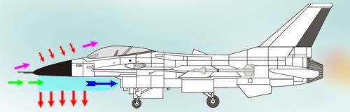
Sample from the current aerodynamics - 7th August 2019
The picture from popular F-16 fighter ( USA ). Jet has he air inlet in the worst possible place.
The inlet creates big under pressures under body and wings. The air inlet boosts the fall and required engine an awful lot.
You should always take the air for the engine from the above of wings and body.The front creates another force that pushes plane towards ground. When possible you should place the side projection tilt to the bottom plate.
F16 in the picture has front for bottom and sharply tilted front for top. F16's front creates overpressure to top and neutral pressure to the bottom.
- you can improve drivers vision with optical windows and cameras. Optical mirror system gives pilot and shooter 1-1 sight.
- cameras and lens systems twist sight a little, tubes for delivering the view are small.Plane is designed for horizontal air resistance, without any attention to ( then unknown ) vertical and reversed air resistance system.
Body's pressure system is also a new thing in plane's aerodynamics.From the diagrams I had from military jet fighters, French made Mirage was the only plane that took air from the above the wings..
Both super sonic airliners, Concorde SST and Tupolev TU-144 have also the air inlets under the wings. Mirage has wings at the bottom.
All US and most Soviet-Russian planes had wings attached to the top of the body.In flat floor military plane you have wings at the bottom. In bi-plane you have wings at top and bottom.
In bi-plane steering system is in between the upper and lower wing.
Cold-jet plane can be steered with boat like flap in thrust.