February 20th 2020


| R&D Vehicles | Fric Full Copter Star G-GPS Combustor Ethene Liquid | Cars Jets Fast Fees Futu ATS | Jack Answers |
| |
Liquid fuel engine February 20th 2020 |
|
| Tights | Page is not yet finished. |
Would be nice if you acquired your licenses before launching first low fuel ratio engines. You need the license right after first tunings.
The presented system and ratios are valid to all oil fires. Petrol, diesel and jet engines. Gas and petrol power plants. And so on.Liquid fuel engine is a name for next generation engine. Name comes from the original idea to put liquid petrol-diesel into cylinder. Vaporize and expand the fuel right before firing. Usage of liquid fuel increases the produced pressures an awful lot. When you run Subaru's 2.5 liter engine at 2500 rpm, gas form fuel produces around 36 bar pressure. When you vaporize the fuel in cylinder the maximum theoretical pressure raises to 760 bars. At 5000 rpm liquid fuel version produces 3 300 bar pressure force, current version produces around 150 bar force system.
During the development it turned out that engine's poor fuel efficiency comes from the amount of fuel, you put into engine. Engine from 2010 uses 1/25 - 1/40 fuel air rations. Theoretical maximum is around 1/100 000. In Gas form the reality optimal mixture with 0,0206 cc petrol fills 30% from cylinder's volume and petrol's share from total volume is 2%.
In engine, fire has two demands. Fuel must have enough energy for heating and expanding the fuel-air mixture. The density of the fuel drops in the mixture must be big enough for maintaining the fire. Fire is chain reaction, After you set a group of fuel molecules into fire, the created heat lights up all nearby fuel molecules. Chain reaction continues until all reachable fuel molecules are burned. In theory you can always split fuel into so small particles, that you get 450C temperature to all air molecules in the chamber. Requirement for fuel molecule density comes from air's heat transfer speed. Cold air transfers heat with around 0.01 mm / millisecond. In 450C air, heat moves around 0.2 mm / millisecond.
When you optimize fuel usage for heat creation, the meaning of liquid fuel falls into marginal levels. When fuel-air ratio is 1/100000, the earlier 150-3000 bar system falls to 150-180 bars. With water booster you can get the earlier 150-3000 bar advantage.
In engine, fire is a method for expanding air. The power comes from the pressure you create into cylinder.
Filling of the cylinder begins the preparations for fire and pressure creation. 100% filling comes simply with opening of inlet valve. When you move piston downwards, the created small vacuum fills the cylinder and balances the pressure in cylinder and inlet manifold. Free filling consumes around 5% from engine power-pressure. In current system you use latch for partial loading. With latch you limit the amount of mixture, that goes into cylinder. The maximum vacuum is 20% - 30% from full volume.
During compression stroke you pre-compress the fuel-air mixture. The compression is not free, it takes around 5% from engine's power system. Compression system goes so, that high compression ratio has always better efficiency ratio. In partially loaded engine, compression stroke begins with filling of vacuum, you created during inlet stroke. The created vacuum reduces the compression ration at the end of compression stroke. The vacuum you create during filling, shifts the compression work. Roughly saying the filling-time vacuum costs as much as compression. The vacuum moves part from compression work to filling time work.
In liquid fuel engine you start to mix the fuel into air during compression stroke. Water booster is always activated after compression stroke, at the same times with ignition.
Firing stroke begins with ignition, which made 10 to 20 degrees before piston reaches top position and changes direction. Fuel-air mixture must be ready before firing. Fire doesn't move mixture molecules much. During expansion mixture keeps original order, the expansion increases distance in between molecules. Asymmetric advance of fire causes small changes to the original order.
Water booster should be closed soon after ignition. After water vaporizes and fuel has burned, pressure inside cylinder raises to sky high levels. Valves for fuel and water nozzles should be have shape and system than valves. Pressure pushes valve towards head and tightens the sealing.
When freely aspirated engine has properly dimensioned exhaust system, exhaust stroke doesn't need significant amounts power. Exhaust system must be capable of emptying cylinder before next exhaust stroke begins. With vacuum in exhaust pipe you can speed up the emptying. Turbo charger brakes the flow of exhaust gases. When you install turbo and set the power-pressure system you take from exhaust gases, you must ensure, that you do not disturb the emptying of the cylinder. When you take too much kinetic power from exhaust gases, you use engine for rolling the turbo. Each rpm and load system has it's own maximum pressure for turbo.
In electric turbo, you don't need waste port for high rpm. Amount of pressure-energy you lead into exhaust system grows with rpm. Mechanical turbo wastes the biggest pressures and powers. With electric turbo, you can adjust the amount of electricity you brake from exhaust gases. Electric turbo needs own battery and electric system. Common generator battery system responses to electric power consumption. You cannot time-shift production-consumption system. Exhaust pipe's generator, should be made so, that it can be used as motor. In motor mode you speed up the emptying of cylinders with vacuum. At high rpm the pressure, which comes from cylinder can 5 bars or more. Mechanical turbo limits the pressure to around 1.5 bar. It wastes 3.5 bars. After compression stroke cylinder should have around 1 bar pressure. Or at the same levels with standard filling vacuum. Big vacuum at the end of compression stroke results to waste of fuel and money. Overpressure limits the amount of gas, you get into cylinder during inlet stroke.
Hydraulic camshaft ( fixed 22nd March 2020 )
When you replace camshaft with hydraulic system, you can get rid of vacuum creation during inlet stroke. An attempt to create such vacuum in cylinder costs quite a lot.
The vacuum without correction comes in progressive form. You convert progressive curve to linear simply by dividing the progressive value with one. With linear pressure you can calculate negative under pressures with the same formula than over pressures.
In conversion 0.1 bar absolute air pressure converts into -10 bar linear pressure. When cars compression ratio is 10, the pressure after compression is around 10 bars. The vacuum system stops the engine at around 0.2 bar absolute pressure or 20% filling. Typically engine's idle filling is 25% to 35%
In current partially loaded engine you sort of waste the energy-pressure you get from standard fire. Instead of vacuum, you should always limit the volume, which has burning fuel. In the new system, you fill the cylinder with fuel-air mixture, which has just enough fuel for warming the air.
In new rolling, hydraulic and double piston blocks, you can adjust stroke length. After you filled the cylinder, you change the direction or ignite the mixture.
In 4-stroke engine and mechanic double piston block you can use CPU controlled hydraulic outlet valves and nozzles for spraying fuel into cylinder.
- During inlet stroke, you fill cylinder with air.
- You open the outlet valve in the beginning of compression stroke.
- Push the air into exhaust pipe until the desired filling ratio is achieved.
- You spray the fuel into cylinder after you close the outlet and before the fire.When you replace vacuum with limited volume, the idle rpm falls. Idle engine takes the latch in air inlet much more seriously than loaded, running engine.
Hydraulic camshaft needs exhaust pipe system, where you do not have overlapping inlet and outlet strokes. 4 cylinder engine needs two separate exhaust pipe systems. High rpm engine needs separate pipes for each cylinder.
You operate valves in 1 to 4 bar pressure. In hydraulic camshaft you can keep the springs, replace only the shaft with hydraulics. You can build a mechanical roller, which simulates shaft, when CPU system malfunctions. You can build brake like small independent hydraulic system for valves, pressurize the system with engine. When you do so, the system becomes functional during start up. Hydraulics without lubrication are pretty much the same than mechanical system. Leaks replaces mechanical faults.
Turbo charger and mechanic compressor
When you look at the sheet and the way engine works with partial load, chargers reverse the idea of traditional vacuum filling. You push pressurized mixture into vacuum cylinder. With hydraulic camshaft you get rid of this contradictory behavior in partially loaded engine.
You have hydraulic camshaft, 2 bar charger, 500 cc cylinder and 100 cc fire chamber. With hydraulic camshaft
- during inlet stroke, you fill 500 cc volume with continuous 2 bar pressure
- you continue the filling and gas exchange to the compression stroke. You keep both valves open.
- after you close outlet valve, you start to compress 2 bar mixture. If you closed outlet at halfway, you compress 250 cc / 2 bar volume into 100 cc volume.
- the pressure after compression is 2 bars * 250 / 100 = 5 bars.
- with firing you raise 5 bar pressure into around 10 bar theoretical pressure.
- then you extend 10 bar and 100 cc theoretical volume into 500 cc volume.
- the wasted exhaust pressure is around 2 bars.
Power-pressure creation
When you create power or kinetic pressure, you play with volumes. The primary unit is bar. Atmospheric, gravitational pressure is 1 bar. When you compress 1 liter volume at 1 bar pressure, the compression ratio is pressure in bars. Shrinking 1 liter to 0.5 liter results into 2 bar pressure. Compression to 0.1 liters results to 10 bar pressure. When you have 1 liter box with 5 bar pressure, compression to 0.5 liters doubles the pressure, after compression pressure is 10 bars. In bar based calculations you use centimeter as base unit. 1 bar = 10 N/cm2.
When you play with volumes the area changes from push area to walls total area. In cylinder the area for pressure comes from pistons area, cylinder walls area and heads area. Pressurized volume pushes all walls with the created pressure. When so :
Area for cylinder's kinetic pressure force = 2 * Piston's area + 3.14 * pistons diameter * height of volume.
- height of fire chamber comes from fire chambers volume and piston-cylinder area. Height = volume / piston area.In combustion engine :
- During inlet stroke cylinder gets the same pressure, you have in inlet manifold. The time you keep inlet valve open is insignificant. The actual filling and initial pressure comes from design. Actual filling can be taken to notice with filling efficiency factor.
- Volume for compression is cylinders displacement volume + fire chambers volume. Fire chamber volume comes from compression ratio. Compression stroke scraps the displacement volume from total volume. Compression of gas is not free from losses. In petrol engine compression could raise temperature with around 40C. When so, during compression mixture expands 10 to 15%.
- During firing you expand the compressed volume. When you calculate produced forces, you must remove the force you used for creating the initial pressure. And also the force, you used for compression time gas expansion.
- Fire's temperature is around 450C. Air's density at 450C is around 0,49 kg/m3. Compression work raises temperature-density system furthermore. Mixture doesn't get much heat from cylinder walls. At 20C heat moves 0.0936 mm in one millisecond. After fire air speeds up to around 0.216 mm / ms. Heating of 1 kg air in 2 liter, 4 cylinder petrol engine takes around 150 J. Typical energy portion from fuel is 500 to 1000 J.
- During exhaust stroke you waste part from created pressure. The leaked pressure is equal to pressure, you have in cylinder, when you open outlet valve. The volume, you don't remove from cylinder is burned fuel-oxygen-air mixture. When so, this volume adds to filler gases in the fuel-oxygen-filler mixture. It reduces amount of oxygen in air. When so, it reduces also the amount of required fuel. 0.5 bar under pressure in exhaust manifold halves the amount of burned gases in cylinder. The volume of burned gases is dependent on pressure in exhaust manifold. With 1 bar pressure volume is fire chambers volume.
Comparisons - March 2nd 2020
Lotus - 123 .. Excel - XLS yve_powersheet_Peugeot_308_2010_16VTi.WK4 yve_powersheet_Peugeot_308_2010_16VTi.XLS - progressive vacuum, water booster yve_powersheet_Subaru_Legacy_25is.XLS - has vacuum handler Audi RS5 V8 2010 - misses calculations for inlet stroke vacuum Power sheets
- the sheet files are not compressed. Sheets are prototypes.
- power calculations are pressure calculations. Pressure is a force, which affects to one square meter area. When you create 10 bar pressure into cylinder, the creation of the pressure is independent from the material, into which you create 10 bar pressure. When you compress air, pressures and volumes matches. In liquids and solids the required volume change for 10 bar pressure is very small. When you remove progression from vacuums, you get into simple linear pressure-volume system.When dealing with table data : After you close the cylinder for compression and firing, molecule counts remain unchanged. The inlet temperature-density system sets the amount of fuel-air mixture you have in cylinder. In calculation expansion-pressure comes from density changes at inlet pressure-temperature system. When density doesn't change freely, gas expansion ( falling density ) converts into pressure.
In the calculation fuel and oxygen atoms which are used for burning are separated from common air. These are converted into water and carbon dioxide.
Heating from compression
Temperature raise from compression comes with original density. When gas is compressed in closed volume, you can calculate new density for the gas. After you get new density, you need density table for the compression pressure. From this table you search density, which matches calculated density. Since there is only one density-temperature system per pressure, the new temperature must be value, where calculated and table values matches.
When you compress 20C air to 10 bar pressure, the density raises from 1.2 to 12. At 10 bar pressure, air's density is 12 kg/m3 at around 50C temperature. According to the tables diesel engine's 1:20 and 20 bar compression from 20C temperature, results into 30C temperature-density system. Diesel engine must get over 300C hike from compression. Otherwise it cannot run. With 20 bar pre compression mixtures density raises from 1.2 kg / m3 to 24 kg / m3. Tables are obviously calculated with some formula.
In pressure sensor engines and water boosters heating from compression must be checked. Aluminum melts at 660 C, softening begins before the melting. Copper melts at 1080C, cast iron at 1200C and steel at 1400C.
Missing gas form
Key thing is power calculations was missing gas form for common petrol. After petrol and diesel converts to gas, their name converts to ethene or ethylene. Chemical formula is C2H4. The longest common gas form oil string is butene - buthelene. It has 4 CH2 molecules in it's strings. Liquid petrol has 5 or more CH2 molecules per string. Solid sugar has 6 molecules per string.
Typically liquid form is standard for pressurized gas. Pressure raises boiling point and lowers melting point. Vacuum lowers boiling point and raises melting point. Fuels keeps their form very well. Range where fuel can exist in both gas and liquid is almost 100C. Petrol can convert into at around 25C. After 215 C petrol is always in gas form. After you vaporize petrol, it converts back to liquid, when temperature falls below -115C. Diesel is enhanced so, that lowest gas point is 180C and highest 360C.
At atmospheric temperatures and pressures petrol and diesel can always exist in both liquid and gas forms. Water is an example from the compound, which has only one melting and boiling point per pressure. At atmospheric pressures and temperatures water can exist in solid and liquid forms. Gas form is possible only after around 100C.
Upgrade to driving forces - March 22nd 2020
When you scrap water booster from Peugeot 308 sheet and match the power creation to 50 km/h speed ( with transmission efficiency ), you notice that resistance grows too much with speed. With 0.6 efficiency engine produces 1.82 kW and needs 1.81 kW for 50 km/h speed. When you increase speed to 120 km/h, wheel power is 18 kW and need is 23 kW. The fault grows from 0% is 28%. ( In this sample air resistance is calculated with 1.20 density for air, density is not in the formula in the downloadable sheet ).
Air resistance
The air resistance system for Peugeot 308 from the year 2008.If you use four directions for the force
- at ground level yellow downward escape is almost non-existing. The downward escape creates over pressure under the body.
- green and cyan sideway escape moves air sideways.
- magenta arrow moves air to hood.
- the red arrow is accumulating force. It pushes pressure wall in front of the car.
- blue arrow is a vacuum force, which drags car backwards.
- pink arrows are pressures, with what air pushes body.
- black arrows are force vector directions for body.After hole creation sides and roof carries the pressure. Side pressure doesn't have much meaning. But roof pressure increases cars weight and rolling resistance. The mismatch in air resistance formula obviously comes from down force. Down force direction is in 90 degrees angle. The power of three for speed needs adjustment.
From the back comes third speed related pressure-force system. The closing of the created hole forms under pressure to the back. In picture like hatchback, rear vacuum is the biggest pressure-force system, which resists movement.
When you increase speed, the size of created hole grows linearly. But the volume into which bigger hole affects grows in all three dimensions.
At 100 km/h speed mass of air in the hole is around 100 kg per second. Hole making force matches 1 500 kg weight.In air resistance formula 0.5 should be connected to air's density. 0.5 is air's horizontal viscosity. It comes from internal around 45 degree angle. Horizontal move of the air needs around 50% from the force you need vertical lift. Force you need for vertical lift is weight * density. When you drive in hills, you should correct this 0.5 with hills angle.
When you drive car, the effective volume is actually a ball. Not a logical box like in formula. In ground and water vehicles the closed bottom converts the volume into elliptic half ball. The oversized box compensates roof and rear resistances. When you use front ball, you must calculate also roof and rear forces.
When you design car like Citroen SM was designed, where the bottom's over pressure matches roof pressure, you reduce air resistance forces with lift force, but you spend power for compressing air to the bottom. Front spoiler, which keeps air away from bottom, improves air resistance factor with 10% to 20%.
With tubes you can move front pressure to back and fill the rear vacuum with tube air. In tubes you do not compress air, you only speed up the air. Air can be accelerated with rather small forces. The required speed up force is calculated with dynamic or kinetic viscosity factors. When tube ends to rear vacuum, the vacuum speeds up air in the tube.
? The viscosity for aero and hydrodynamics is collision viscosity. Collision viscosity tells how liquid and gases moves sideways, when collide with wall. The with what you push the liquid-gas towards wall is much more bigger than the force with what liquid-gas moves sideways. The collision force increases pressure in liquid-gas, after internal pressure raises enough, liquid gas start to move sideways. In continuous flow, you must raise the pressure for each molecule, that takes desired 90 degrees curve.
Rolling resistance
When you push car, it needs around 1 000 N force, before it moves. With feet you can produce 1 000 to 2 000 Newton push force. It is just enough for pushing the car. 2 or more persons do not have much difficulties with the push. Calculated rolling resistance is 100 to 150 N. Friction force is dependent on car's mass. When you assign the calculated G force to tires touching surface you get near 1 000 Newton force. 195/65 x 15 tire is 0.195 meters wide and the length of touching surface is around 195. If wheel pressure exceeds roads capability to carry load, you must use pit factor for correcting the rolling resistance. In new friction system, where tire and surface has their own friction factors, the resulting factor remains almost unchanged. In new system tire gets speed-load curves for friction factor. Speed and load affects to the way tires sides transfer power to touching surface. Soft tire lives, when you change speed-load-pressure. Tire suspends faults in steering and suspension events.
Down and side forces
In order to be capable of adjusting speed, the rolling resistance must change with speed. The change comes from the air resistance.
- Air resistance increases so called down force. This down force is actually an addition to vehicle's weight.
- Another addition comes from front force. This front force is air resistance force.Down force comes from vehicles vertical air resistance.
The base pressure for down force comes from frontal force. Frontal pressure moves into 4 directions. Top-Down and Sides. Down pressure is around 10% from total. Free sides and top gets around 30% each. Air's viscosity drops the down force with around 50% per meter. After 20 meters force stabilizes
On plain surface side forces have very little meaning. In holes for wheels, side pressure extends into hole's free volume. The pressure falls, but it starts to resist movement. Open window has similar kind of effect than holes for wheels.
This viscosity based downgrade is the only thing, that reduces down and side forces. The forces you get from air resistance are Newtons per square meter. When so, you calculate top projection for vehicle. Or a part you are calculating the forces. Downforce grows quite a lot at front window, then it drops at rear window.
Moving object's kinetic energy
When you change speed of object, it's kinetic energy contents changes. When increase speed, you must add acceleration force into force calculations. It is well known, that fast acceleration consumes more fuel than slow acceleration. When I calculated acceleration forces, fast acceleration needed less energy than slow. Another thing is friction, friction should be independent from objects movement. You calculate acceleration forces with mass and current acceleration. When you multiply mass with acceleration the calculation matches potential energy.
In moving object the actual kinetic energy contents comes with speed and mass. The kinetic energy is a pressure system, moving object creates into gravitational flow. All the other forces operates in gases atom mesh.
In turning object, this kinetic energy creates centrifugal forces. It keeps object moving in frictionless volume. After you have created the energy to moving object, the gravitational flow maintains the pressure system.
The force with what you create the speed-pressure system, varies with the amount of acceleration. In curves the kinetic energy comes with speed and mass. Not with accumulated acceleration forces.
Cooling, combustion collectors, aerodynamic tubes, water booster and air humidity - March 22nd 2020
You have two one liter kettles with one liter 50C water. When you mix the water together the resulting temperature remains at 50C. Temperature blends, it doesn't accumulate like electricity does.
When engine has combustion collectors, you don't cool the engine. You try to get fires 450C temperature into combustion collectors. You choose sealings and set the tolerances so, that engine can run without cooling. You cool the outer surface of the block and head with the air from aerodynamic tubes. These tubes are always open. You speed up the flow at higher speeds, when air resistance force starts dominate force system.
Engine has two sets of combustion collectors. One set surrounds cylinders and takes heat from block, second set grabs heat from exhaust gases. Exhaust pipe needs system for collecting water-steam from the exhaust gases. You can for example cool the exhaust gases so much, that water converts back to liquid form. Then you have small water collector near the end of exhaust pipe. Water collector should be adjustable. With adjustable collector you can increase and decrease local humidity. By default you collect water booster water into tank. And let the humidity, which comes from fire into air.
You could have 10 million city, with around 5 million motorists, who drives 10 km per day. This results into 50 million km per day. If car consumes 1 l / 100 km, the daily fuel consumption is 500 000 liters. This converts to around 1 million liters or 1 cubic kilo meter of aired water vapors. If you get around 20% from the produced vapors to humidity, the addition is 0.2 km3 a day. With 2% absolute humidity, private cars vaporizes around 10 km3 per day. Currently private cars vaporizes around 70 km3 every day. At around 1970 Californian king sized cars aired humidity to around 150 km3 volume. With water booster, you can compensate the losses in air humidity.
If you build engines corrosion proof, you might be capable of using salt water in water booster. Depends on exhaust emissions. Otherwise salt water suits better into water booster. Engine burns the salt ( with flames ) from water.
Optimal fuel-air mixture
The optimal fuel-air mixture has just enough fuel for warming and expanding the air in the cylinder.
Engine design plays big role in fuel drop distribution. And also in the amount fuel, you need for warming the air.
In partially loaded engine, you can use fuel clouds for heating only part from the mixture in the cylinder.
In cloud system, you burst fuel into air right before you close the inlet valve. So that the clouds are near spark plug and each other.When you produce pressure, you take advantage from heat expansion and you use the source pressure.
The created pressure-force system is relative to volume change. You sort of pack the volume change as force into the gas you compress.
The pressure-temperature system follows the packing system.In gas form all fuels burns with 425 C temperature. The rest comes from increased pressure. As liquid, diesel burns at 250C temperature. 95 petrol at 300C. 98 petrol at 400C. Fly petrol at 500C. In 4 stroke petrol engine, you should use 10 bar curve for defining the expansion, and in Diesel 20 bar curve. Two stroke engine doesn't compress air. At the bottom of the page there is big diagram from densities at various pressures.
As you can see from the diagram, the expansion ratio falls, when you increase the source pressure. When you bring 20C mixture into cylinder, the volume gets 2.5 times boost. With 300C start up, boost is only 1.5. Samples 300C is said to be the internal temperature in cylinder walls and piston.
Pressure up to 500 bar has very little meaning to heat conductivity. Temperature change from 20C to 500C doubles the conductivity. Hike from 500C to 1000C gives 50% boost. The compression reduces the distance in between atoms. Compression ratio 1:10 heats the gas 10 times faster than uncompressed volume. Mixture burns 10 times better. Since engine's fuel efficiency is 0.2 - 0.3, higher compression ratio allows you to reduce the amount of fuel, you need for fire and power production.
In liquid fuel tech, you can use hydraulic compressor for filler air and fuel-air mixture. Hydraulic compressor can be controlled just like electric charger. Hydraulic compressor can have fault free basic compression system. System, which works without electric controls. Since fuel's share from cylinder's contents is so small, you can prepare fuel-air mixture for fire. And spray the ready made gas mixture to cylinder.
In principle water booster engine has three rounds of gases. Inner round sprays fuel-air mixture around spark plug. Middle round has filler air. Outmost round is made with water sprayers. Water is around 5 times better heat conductor than air. Water vaporizes right after it touches cylinder walls. Round of air, prevents water from disturbing the fire.
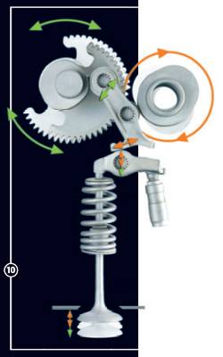
Adjustable camshaft-valve system - March 14th 2020
In the picture you see camshaft system from Peugeot 1.6i, 2010. In the system inlet valves opening length varies from 0.25 mm to 9.25 mm. Inlet system is traditionally controlled with carburetor. In the air inlet tube there is a big latch, with what you adjust the filling ratio. In other words system is useless. Engine is not very economical.
When you have a hydraulic camshaft and springs in valves, sway-switch above the valve-spring is replaced with hydraulic cylinder. All the other things are scrapped from the head. Hydraulic camshaft is compact, simple system.
In high-rpm engine, where you use hydraulics for lifts and pushes, the hydraulic cylinder needs gas spring system, with what you push the cylinder towards head. With out gas spring, hydraulic lifter breaks the head. During the time valve is closed you load the gas spring with small hydraulic pressure.
Both hydraulic camshafts works without lubrication. In head, camshaft is typically the only lubricated part. Valves up'n'down movement is usually lubricated with fuel, not with motor oil.
Hydraulic camshaft removes need for oil channels in block. With oil pump you lubricate crankshaft bearings, then you splash oil to cylinder walls and piston's bottom..
Pressure-power system for compressed volume - March 7th 2020
As you can see from the picture on the right, engine's pressure-power system grows linearly with revolution speed. But the powers grows very quickly. The fast growth comes from compression.
- When you compress air with 1/10 or 1/20 ratio, the logical expansion volume remains unchanged.
- When you burn and expand the mixture in 10 bar pressure, with 2 x expansion, the pressure peaks to 200 bars.Without this peak, the calculated powers at high rpm falls far behind measured presses. When Audi V8 produces 335 kW at 8250 rpm, without peak the calculation gives you only around 70 kW engine powers. But when you set peak pressure to around 150 bars, the calculation gives you a close match to measured powers.
Audi's top speed is 250 km/h. With this speed the calculation results into 25 liters / 100 km fuel consumption ( fuel-air ratio for this consumption is 1/35 ).
Due to switch effect, small change in mixtures expand ratio causes a big change in produced engine powers. Audi gives 335 kW with 1.78 expand ratio. When ratio is 2, power is 380 kW, with 1.5 power is 276 kW. With 1.7 ratio the temperature in cylinder is around 600 C. Hike from 20 C to 600 C results into 1.7 change in air's density and expansion.
Liquid fuel engine and oxygen extractor
Double piston system for liquid fuel engine can operate all the time.
You fill the cylinder at the same time with fire. Just like you do in jets.
Liquid engine can have 3 or 4 strokes. It doesn't need compression stroke.
It not easy to construct a system for 3 strokes. You can convert 3 strokes to 2 strokes with pumps.
You use pumps for filling the cylinder with new mixture. The pump can be powered with crank system.
When you use pumps, and oxygen extractor, you get better efficiency to firing event.
With picture like system it is easy to optimize firing, you can use additional sparks for improving the fire.Dropped compression stroke improves engines efficiency a lot.
This system makes it easy to shift into new engine. It will remain as engine for heavy duty double piston transmission.
Mechanic and hydraulic pump transmission can use rolling blocks. Rolling block rotates axle without crank systems.
Rolling block allows you to build 3 stroke engines and engines with traditional compression system.Developed and introduced rolling blocks for combustion collector.
- Rolling block has moving push plates, which prevents creation of reversed forces.
- Rolling block has equal durability and sealing efficiency than piston block.
- Rolling block can be used in closed gas and liquid turbines.
- Block always empties the whole volume from used or burned gases.
- Small minus can comes from continuous movement of gases.
- Block has the same parts and systems than 4 stroke engine. Only the crank system is missing.- - - -
We know how fire works with CxHx and Oxygen. Fire's chain reaction needs around 300 C temperature. Human body seems to burn fat with much lower temperature. The cells seem to burn fat at 37 to 50 C temperatures. The system for cells chain reaction is unknown to us. Possible that closed system, where you have only oxygen and CxHx, works at low pressure-temperature and begins with marginal energy boost. Combustion engine consumes lots of energy to raising the temperature-pressure system for the fire.
When you bring CxHx to cell as liquid and vaporize fat, the volume grows a lot. One fat liter weighs 0.83 kg. When fat-ethene is vaporized, one cubic meter or 1 000 liters weighs 1.26 kg. During vaporization the volume grows from 1 liter to 660 liters.
The lowest boiling point of fat is 25 C. After vaporization, liquid fat's boiling point falls to -100C. Methane converts to liquid at -160C, after conversion to liquid, methene's boiling point raises to at least 50C. This system is unique to CxHx compounds. Hydrogen is gas, hydrogen atom can stretch and shrink rather freely.
In principle you should be capable of creating an engine, which vaporizes gas during the firing stroke. When you do so, one liter fuel-air mixture ( with 1/14 fuel-air ratio ) converts into 40 liter mixture. The compression ratio is 43. German combustion engine vaporizes the fuel in inlet or during compression stroke. You can alter the system so, that you spray cold liquid fuel into cylinder right before firing and after compression stroke. When you do so, you vaporize the fuel with fire.
In liquid fuel engine, you don't have to compress air. Compression stroke is used for moving the piston to right position.
Liquid fuel system suits well to jet engines.If you can drop engines' operating temperatures to 200C, 100C or 50C, traffic's effect to global warming falls a lot. Current operating temperatures are 500 to 700C. With 40 to 50 C operating temperature, traffic's emissions are almost perfect match to natural emissions from humans and animals. In order to keep low temp engine safe, you need fuel, which burns only in cylinder.
Can for example use air filter, which extracts oxygen from inlet air. So that the fuel needs 30 to 40% oxygen levels in the air. Lungs extracts oxygen atoms from the air and mixes them into blood. It is not known how. Oxygen and nitrogen atoms are almost perfect match. Nitrogen is kind of an inactive form of oxygen. Some component in blood might create a compound with oxygen and convert oxygen in to liquid form. Pressure changes could demolish the weak compound and release the oxygen. When cell acts and burns fat, pressure releases the oxygen from the temporal compound. Blood with oxygen bubbles in fast pressure changes. Petrol-Oxygen ratio is 1/3. With oxygen extractor 1000 cc / 1 liter engine shrinks to 200 cc engine. Liquid fuel downgrades the size furthermore. Engine sizes got stuck in 1950s and started to grow in 1960s. First Porsche 911 had 1.6 liter engine.
With oxygen extractor optimal mixture is 1/3. When so maximum compression ratio is 660 / 4 = 1 to 165 or 165 bar. When size of combustion chamber is 1, and size of displacement volume is 5, the maximum pressure with biggest volume and fully burned mixture is 165 / 6 = 27.5 bars. With common air maximum pressure is 43 bar. For the same 27.5 bar pressure, the size of displacement volume is only around 0.6. With oxygen extractor exhaust gases are top-notch quality gases. CO2 and H2O are almost the only things, which comes out from exhaust pipe. The amount of hot gases is marginal, when compared common car.
In engine the pressure grows, until push force matches resistive forces. After that piston goes down. The movement increases the volume and need for gas expansion. If the pressure is bigger than resistance, piston accelerates until forces are a match. When you accelerate, the exhaust manifold pressure grows. This wasted pressure increases the fuel consumption in accelerations. During acceleration resistive forces growth is marginal. With electric turbo you can collect acceleration pressures. Common turbo increases the pressure losses. Common turbo raises the pressure in cylinder. Electric turbo stores the leaked pressure into battery.
Oxygen extractor has lots of usage. CO2 furnace is one example from the users.
In liquid fuel engine, you cannot reuse ethene converter's gases. You must lead the converted oxygen and ethene into exhaust pipe. In principle it is better to leave the engine without ethene converter. Ethene is not a natural gas in our atmosphere. If engine leaks ethene, you should burn it into carbon dioxide and water, before letting it out from exhaust system.
It is obvious that ethene emissions contributes to global warming. Catalyst converter obviously increases ethene emissions. Fuel-air mixture is not optimal. Ethene cleaner in exhaust system needs air inlet and firing system. Or alternatively recycling system for unburned ethene fumes.
Ethene doesn't fall from the sky like water and carbon dioxide.
Water conversions
Water is another thing you can vaporize in vehicles. One liter water weighs 1 kg. One cubic meter water vapors weighs 0.6 kg. When so, in closed cauldron one water liter converts into 1 667 liters of vapors. Pressure raises to 1 667 bars. When you use water conversion in combustion collector, you can get the collector into compact size. One liter ethene weighs 1.26 kg / m3. Water is quite a lot better in liquid-gas conversions.
With hot water spray and fire time vaporizing you can get quite big boost to engine's the pressure-power system. This water boost is almost free of charge. The water spray must be directed and timed so, that water doesn't hinder firing. You could build an internal water cooler system to the sides of cylinder.
Water vapors can be used for filling the cylinder's bottom, when engine is not running with full power. Vapors volume-weight changes are modest.
Combustion stroke handling
With combustion stroke engine increases the volume of the burned air-fuel mixture. The volume of burned fuel-air mixture matches cylinder's displacement. In liquid fuel engine, you feed and burn new air-fuel mixture during piston's movement. You control the feed with pump and cylinder's pressure sensor. You cut the feed before you open outlet valve. With pump, engine never ends into situation, where it cannot raise rpm. Happened with IMMO all the time. With hydraulic or electric, properly dimensioned high pressure pump, you can increase pressure independently from engine's current state. You can temporarily exceed constructional maximum pressure.
Oxygen extractor and tubes + heat load
Oxygen extractor doesn't reduce the amount of inlet air. With oxygen extractor you divide the air to oxygen, which goes engine and other air, which used for cooling and lead out as it came in. The amount of warmed falls from 15 to 4 which means 70 % drop in heat-load. Heat-load, which warms the air and climate.
Impossible fuel air ratios - March 3rd 2020
IMMO
80 km/h
4 500 s
75 min
5,5 l/100km
2 000 rpm
300 000 firings
0,0183 cc / fuel per fire
0,2567 cc / mixture
32 680 000 Joules / lit
179 740 000 J / tot
599 J / fire
39 942 W - power from fuel
In this table you see interesting impossibility about fuel air-mixture. When I made comparison tables, checked the system with IMMOs known values.
System was fairly close match. But fuel consumption with 1/14 ratio rose to sky high levels, fuel efficiency fell from 20% to 1%.
Due to this calculated volumes for IMMO measured fuel consumption. IMMO uses 18 mm3 fuel for one firing event.
This is 0.05% from displacement volume. Fuel-air ratio is 1:40In gas form the ratio is 1:40. With 80% filling ratio is 1:37. With 70% filling ratio is 1:32. Such filling system is entirely impossible. The system must go so, that that filling range varies in between 70% - 100%. With actual ratios you burn random oxygen atoms from filler air.
The books say that fuel burns with range 1:3 ... 1:25. Theoretical need for air is 1:14. The earlier 1:40 mixture is possible with spark plugs and self ignition systems. Spark plug ignites loose fuel drops in the mixture with electric heat. When so, fire spreads to cylinder as ball, whose origin is in spark plug. In diesel pressure ignites the loose fuel drops.
The optimal fuel-air mixture has range. Range begins from 1:14 and it ends to somewhere near 1:80000. IMMO gets into difficulties after RPM falls below 1 700.
Small share makes it possible for cars to stand in traffic lights during rush hours. You can reuse the exhaust gases, before air runs out oxygen.
- Small share makes it impossible for fuel injector manufacturer to measure oxygen levels from exhaust gases.
- Cyanide emission producer cannot need additional oxygen. After engine has burned all fuel, it has consumed around 4% from the oxygen in the air.-------------------------------
There aren't tables and curves for checking how much compression increases air's temperature.
- The basic curve set starts from 1 bar and -20C to 100C , then it shows how temperature raises when pressure raises.
- Another required set starts from compression pressure and temperature. The set must simulate CxHx fire. In combustion fire you raise both pressure and temperature.
- Spark plugs firing effect should be checked.
- Common glass melts a 700C, from fireproof glass you make transparent blocks and heads for examining engine and individual engine designs. Pyrex is the most common fire-proof glass. Glass engine would need transparent lubrication.
In upgraded engine the liquid fuel and water system must be capable of spraying the liquids in 8 bar pressure. In practice, when you upgrade an existing engine, you reshape cams so, that inlet valve closes after pressure is 2 to 4 bars. Then you limit fuel and water sprays so, that maximum firing pressure stays below engines constructional limits. With sample engine's 16 bar maximum and 2 bar compression, you almost double the force per one firing. Diesel engine's maximum pressures are around 40 bars.
In widespread commercial use liquid fuel engine needs efficient air filter system. In new engines you can adjust stoke lengths. Typically you need 4 or more rolling cylinders per engine. With 4 cylinders the minimum stroke length is around 25% from total length. With 4 cylinders and 25% stroke, you can get power throughout the round. With 4 cylinders you can also use one chamber per cylinder. You can balance the engine with cylinders. Full length chamber maximizes the expansion volume.
Double piston pump engine can also be made with variable stroke length. Typically you move the pistons upwards with hydraulics.
You should develop and build water collector into exhaust system. Cool, liquidize and reuse water.
Adjustable collector allows you to control air humidity.
In the table you see new power and fuel calculations. This is made with
calculated enormous fuel-air ratio. In reality IMMO uses around 15% from the
available fuel energy.
The calculation brought 5.94 kW net powers. Driving resistances are 5.64 kW.
The parameters for calculation were adjusted with known 5.5 liter fuel
consumption.
No matter how you change the parameters, the produced power does not change
much. This check-out table misses water booster.
Since results matches, calculations should be near truth.
Lotus 123 Me adds the sheet data into table. Program does not use the
data, when paste a copy from this table Lotus 123 Me.
HTML source has the spread sheet data as 123 created the HTML table.
This table uses gas form density in fuel section. It should be liquid density, this makes the energy portion look faulty. The fuel conversion from liquid to gas should be made in fire section. Sheet needs the liquid form in the beginning for comparing the calculation and reality results. In order to get good distribution deal for oil, you should vaporize oil before mixing it with air.
Poor fuel efficiency of the combustion engine comes from fuel, which is not used for heating and expanding the air.
Heating of 1 kg air from 0 to 500 C needs 140 J. In the sample IMMO has 0.00072 kg air. With these you need only 0.1 J for heating.
One milliliter fuel has already 32 joules. In gas form 32 J volume grows quite a lot, to 0,60317 cc.Heat moves in oil fire with 0.2 mm / ms speed. In order to secure fire, you need 25 fuel drops in one mm3, and 25 000 drops for cm3. In order to ensure total fire, you need drops for whole volume. It makes 14 043 000 drops.
With 1 / 179000 ratio you get fuel efficiency to 100%. But this is not the maximum. Maximum ratio is somewhere near 1 / 17 millions.
You should not have difficulties with an upgrade to 1 / 90 000 ratio. With this ratio you have still 200 J for heating. This ratio drops the fuel consumption to 1 / 3 from current.When you burn fuel and warm air, you charge the cylinder and exhaust gases with heat energy. In cylinder you take advance from heat expansion only.
Combustion collector converts the wasted heat energy into kinetic or electric energy.
Collector works with lower temperatures and it needs water booster for reducing the size of collector system.