
Liquid fuel engines - March 16th 2020


| R&D Vehicles | Fric Full Copter Star G-GPS Combustor Ethene Liquid | Cars Jets Fast Fees Futu ATS | Jack Answers |
| |
Rolling
Block Engine Liquid fuel engines - March 16th 2020 |
|
| Tights | Page is not yet finished. |
Rolling block is efficient way to rotate axles. The cylinder-piston system is mounted directly to rotating shaft.
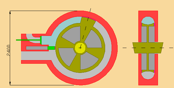 |
In the diagram : Yellow = piston + shaft Red = Block Green = inlet valve and push plate Magenta = loose sealing surface blue space = work space silver space = exhaust space gray space = free space - Pistons push side's tilt angle could vary from 0 to the center
angle of the piston. Center angle moves the theoretical push force into
center of the piston. |
Rolling block never stops or changes direction. Block has two simultaneous strokes, inlet-firing stroke and exhaust stroke. Rolling block has only three moving parts, water booster adds inlet valve for spraying water into cylinder.
In system part of cylinder wall is in piston. Piston consists from tilted piston and the bottom of the cylinder. System suits well big pressures and powers, the carried bottom of the cylinder creates a strong support for the actual piston. The piston itself can be shaped freely. Piston has two faces, and space in between. The first face is the one, that creates the power-pressure system. Another face empties the cylinder from exhaust gases.
Rolling block has hydraulic input valve. Outlet tube can be open all the time. The outlet valve is replaced with push plate. During firing and power creation push plate prevents creation of negative forces. Back side of push plate prevents exhaust gases entrance to firing chamber. Push plate is opened, when piston comes and begins new inlet-firing stroke.
By default you do not compress fuel air mixture. If needed, you can use water booster. Engine does not have fire chambers and displacement volumes. You have filling pressure and ignition volume. Ignition volume is the volume, where you close inlet valve and ignite fuel-air mixture. In freely aspirated engine filling pressure is little over 1 bar.
After ignition the burning mixture pushes the piston forwards, as long as there is enough power-pressure to rotate cylinder. If the pressure is not completely used, when piston passes outlet hole, the remaining pressure is leaked to exhaust system.
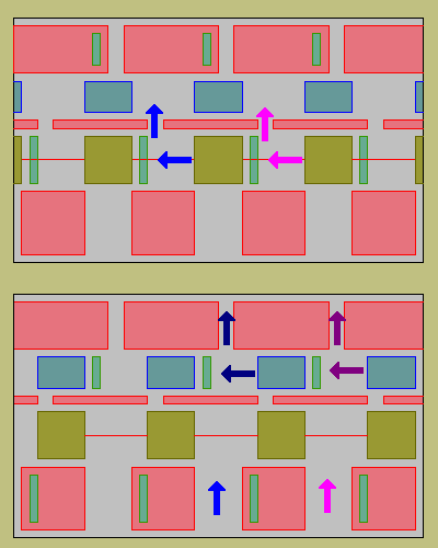
The standard piston-unit has three pistons. The cylinder, where you burn fuel-air mixture is surrounded with combustion collector cylinders. You use the fire chamber for vaporizing water in combustion collector cylinders. Typically you build the three cylinder unit so, that unit rolls around with it's own power creation system.
With hydraulic valves and ignition volumes you can rather easily synchronize powers from fires and collectors.
Sealing-system for cylinder bottom can be as big as you wish. Same goes to piston and piston rings.
Rolling block principle can be used in pumps and turbines, too. The push plate system brings the efficiency at the same levels with straight forwarding piston-rod system. The pressure always searches the weakest point. Without push plate all rotating systems create negative forces. They push the back of chamber. The size of negative force is dependent on design.
The reversed system works as compressor. In compressor you have open inlet. First you fill the cylinder with air. During engines exhaust stroke, you keep the outlet valve closed until pressure is high enough. After pressure raises to for example 10 bars, you control the exhaust pressure and keep it at 10 bars with outlet valve. If you use tank, you don't have to control exhaust pressure.
 |
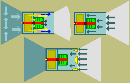
In the diagram you see chained piston-based blower
compressor for jet engine. - Magenta arrow follows the movement of volume 1. - Blue arrows follows movements of air volume 2. - In upper picture the primary input wheel compresses and pushes air to
second wheel. Primary wheels push plates are on, secondary plates are
off. This diagram produces slightly pulsing output. The compressor stops
for the time you operate push plates. In principle you should use only
one wheel systems. The size of final output hole and following system
sets the output pressure. Continuous compression needs a cone alias tube, which narrows towards end. Then you need pump or pump effect for pushing gas or liquid into tube. This pulsing system has built in pump effect. Speed improves the pump's efficiency. Compressor has 2 or more moving parts. All chambers need push plates. You can build camshaft like mechanic system for operating the push plates. Compressors efficiency matches piston-crank system's efficiency. Compressor should work just fine. Thrust comes vacuum in front of the jet and pressure behind the engine. You might want to empower the compressor with it's own integrated rolling engine. Use exhaust gases for increasing the pressure in fire chamber. Also possible to build a jet, where you have rolling engine and only one compressor turbine. Replace the power turbine with rolling engine. You can use the heat from engine for warming and expanding the air and vaporizing water. |
 |
When design engine for plane or aircraft, you try to maximize exhaust pressure losses. At low speed you use the pressure for increasing the lift, at high speed you use the pressure for speed creation. When speed grows, the meaning of air's viscosity falls. When so, need for lift falls with speed. When you create thrust, the thrust creation takes place after tube ends. The free air after the tube creates the counter force. In order to create the actual push force, the tube needs thrust plates. Thrust plates makes the aircraft move. In the upper pictures you see pressure force creation system, and on the right you see the counter forces. Air's escape-viscosity system downgrades the counter forces. Thicker air gives more thrust to both propellers and jets. In lower picture you see counter force system for jet engine with designed and optimized thrust plates. Rolling jet can be made so, that it takes air only for rolling engine. Rolling jet use combustion collectors for creating more pressure from the created heat. Rolling jet can have common water booster. Then it can use water booster for improving lift and vertical air resistance. It can also use water boosters for increasing counter forces. Rolling jet doesn't have special cold-jet version. |
In boats you can use compressor as propel and alternative for earlier screw and double piston propels. In boats exhaust pressure leaks do not improve boats performance or economy. In big ships you typically use double piston engines and double piston propels.
In ground vehicles you can use compressors for crating efficient powered tube systems. At high speeds tube power is more efficient than wheel power. 10 bar compressor needs that tubes front area is 10% from total projection. Engine with water booster doesn't use much air. Without water booster engines use as much air as before. They use less fuel for heating and expanding the air.
Comparisons
Lotus - 123 .. Excel - XLS Power sheets
- the sheet files are not compressed. Sheets are prototypes.
- power calculations are pressure calculations. Pressure is a force, which affects to one square meter area. When you create 10 bar pressure into cylinder, the creation of the pressure is independent from the material, into which you create 10 bar pressure. When you compress air, pressures and volumes matches. In liquids and solids the required volume change for 10 bar pressure is very small. When you remove progression from vacuums, you get into simple linear pressure-volume system.
Machine powered tubes for vehicles - March 20th 2020
Tubes for vehicles uses logical air volumes. First you calculate vehicles front projection. Then you multiply the projection with speed in m/s.
Car width 1.90 m and height 1.5 m makes 2.85 m2 projection. At 100 km/h speed you move 100 / 3.6 = 27.78 m/s. At this speed car pushes away 27.78 m/s * 2.85 m2 = 79.17 m3 volume during one second. If you have two 25 cm x 80 cm tubes, their area is 2 x 0.25 x 0.8 = 0.4 m2. For 100% removal compression ratio in tubes is 7.125. Pumps track speed must be 7.125 times faster than cars speed.
You do not compress air in the tubes, you speed up air. This speed up compresses air, but compression and required forces are much more smaller than in closed volume. When you take viscosity into account, you got to remove around 50% from air. This drops tubes speed requirement to 4 x vehicle's speed. If you lead the outlet air into thrust plate system, you get great deal from the used pump force back.
There aren't tables for calculating the tubes. Pneumatics, hydraulics and others play with compressed, pressurized air and liquids. Tubes are much like wind machines. Overpressure in tubes could be around 50% from compression ratio pressure. This missing intentional compression makes tube power more efficient than wheel power rather quickly. Especially in vehicles with poor aerodynamics.